Transmitted specular
I've been playing with the transmitted specular implementation for IBL, and working on getting the right balance and visual impression for glass.
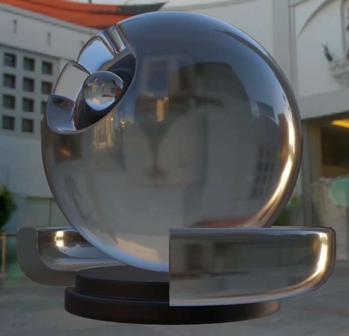
Background textures from http://www.hdrlabs.com/sibl/archive.html
It's curious to think about how terms have changed over the last few years. "Specular transmission" is the term I've been using to talk about what we might have previously called "refraction mapping", and "specular IBL" is the new term for "reflection mapping." The new terms show how real-time methods are now encompassing ideas previously only used in ray tracers.
Basic method
I've using the basic method from the GGX paper, "Microfacet Models for Refraction through Rough Surfaces" from Walter, et al. This matches our reflection implementation, of course, because the math for our reflection method is also based on that paper.
I've been able to adapt the math to the split-term concept used for reflected specular IBL. It works just the same way; we have one lookup-table that tell us the brightness of the refraction, and a cubemap that is pre-blurred according to the shape of our lighting equation.
See the page on Improved IBL for more information that that split-term stuff.
The basic principles are simple. But followed blindly, the results do not quite feel right. It turns out that specular transmission is more complicated than specular reflections. I'll talk about some of the complications involved in the implementation...
Relationship between "specular" and index of refraction
It's important to remember that there is a relationship between the "specular" material parameter and the index of refraction.
Remember that the specular parameter is used to determine "F0" -- which is the brightness of specular reflections in the center of a sphere. This phenomenon of reflections being brighter around the edges of a sphere is driven by the "fresnel" effect.
The fresnel effect determines how light is reflected off a material, and how much gets absorbed into (or transmitted through) the material. Remember that is the ratios of the indices of refractions on either side of the boundary that determine the quantity of reflection and absorption.
So, there is a 1:1 relationship between F0, "specular" and the index of refraction. These 3 values all represent the same physical property.
The index of refraction important to us because it also determines the direction of refraction. And it's important that this agrees with the fresnel effect calculated for specular reflection, because the refraction looks strange if it doesn't merge into the reflection correctly.
So, this means that the "specular" material parameter effects both the apparent brightness of the refracted image, and the quantity of distortion applied to it.
3 parameter lookup-table
Our "brightness" lookup table now requires 3 parameters (one more than the reflection case):
- N dot V
- "roughness"
- index of refraction ratio
Also, the lookup-table can contain values greater than 1 (because refraction can focus light).
Generally it should be ok if specular transmission is less accurate than specular reflections, so I've settled on using a 64x64x32 Float16 texture. This is actually the same total size as the reflection lookup-table.
It should be noted, however, that subtle effects in the brightness of the refraction seem to have a big impact on visual believability. It's important to get exactly the right
Fixed index of refraction?
We can potentially optimize the solution by using a fixed index of refraction for all transmitting surfaces. An ideal number might be around 1.5 (which is glass). The fresnel effect for the transmission should match the reflection case, but apart from that, the quantity of distortion applied to the image doesn't seem very important to visual believability. So it might be sensible to use a single fixed index of refraction for all materials, just to simplify the shader math.
GGX transmission focusing term
Most of the equations in the GGX paper can be brought across as is. However, there is one term that causes many problems.
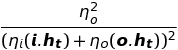
This term is responsible for dealing with the focusing of light. Where the refracted image appears shrunk, more light has been focused together, and so the result is brighter. Likewise a magnified image is darker.
Walter describes the derivation of this term, and explains that is an approximation of the following equation:

Where the straight brackets represent the determinant of a Jacobian partial derivatives matrix. The omega values are angles of the outgoing ray and the half vector.
The core equation is the derivative of the angle of half-vector with respect to the angle of outgoing vector. Remember that the half-vector is a direction somewhere between the incident ray and the outgoing ray. In Walter' equations, the incident ray is constant. So, we can think about this equation as measuring how much the outgoing ray moves as we shift the half-vector. If it moves a lot, we know the incident light is being scattered in a wide angle due to microfacet detail.
There's another interesting approach to this same equation in Jos Stam's "An Illumination Model for a Skin Layer Bounded by Rough Surfaces" from 2001. He mentions that he initially overlooked the importance of a term like this and found that the results looked like they were missing something. So developed his own approximation to this term.
There is a problem with this term, however, because the sampling that Walter is doing is not the same as what we want to do for real-time. In our sampling of this equation, we want the outgoing ray to be constant, and the incident ray will move -- this is the opposite of Walter's sampling.
So, we need to rebuild this focusing term for our needs. We could use the same approach as Walter, and just flip the terms around... But I've been playing with some other approaches.
New focusing term equation
I've been experimenting with an algebraic solution to the derivative equation. Our algebraic solution isn't necessarily going to be perfectly accurate, but the end result appears visually acceptable.
A simple algebraic solution involves comparing "O dot H" to "I dot H" (ie, these are the cosines of the angles between these directions and the half-vector). These 2 dot products are related, and we can come up with a simple equation for their relationship. We can take the derivative of the angles use this as an approximation.
Since O is constant, a change to "O dot H" represents a movement in the half-vector. So this equation tells us how much I changes relative to H whenever H changes.
However, that's not perfect. We really want to know the change in the angle between I and some fixed direction. The simplest solution is just to use O as that fixed direction.
So, we can adjust our equations to find the relationship between "O dot H" to "I dot O". We can then find the derivative of that equation (with respect to the angles involved). This should give us an idea of how I changes when H changes.
Derivative equation
Unfortunately our derivative equation is very complicated. It contains many terms, and many trigonometric operations.
In plain text form, it's:
(a sin(2 x)-(sin(2 x) (a^2 cos(2 x)+1))/(sqrt(2) sqrt(cos^2(x) (a^2 cos(2 x)-a^2+2))))/sqrt(1-(sqrt(cos^2(x) (a^2 cos^2(x)-a^2+1))-a cos^2(x)+a)^2)
... Ok, it's a crazy-looking equation.
However, we're going to be mostly just using it for pre-calculating tables, so that shouldn't be a problem.
This equation is showing the right kinds of effects we expect it to -- we get a brightening around focused areas, and a diminishing around magnified areas.
I've found that I've needed to multiply the results by "4" to get correctly balance. That part isn't clear to me yet.
Also, Walter explains how he is using the determinant of a Jacobian matrix of partial derivatives. However, our derivative equation has just the one parameter. I haven't quite wrapped my head around how that fits in yet.
That said, the results are visually satisfying. Even those there are these uncertainties, I would say that the results are good enough for our needs.
Simplified equation
We can simplify the monster of a derivative equation. By hand, I found that the following equation seems like a good approximation:

Where a the ratio of the indices of refraction. This shows all of the same behaviours as the complex equation. For our purposes, the differences are negligible.
Transmission blurriness
For blurring the refracted image, we could simply build a new cubemap with new filtering intended for the transmission case. Indeed, this is possible. However, given the similarities between the filtering for transmission and the filtering for reflection (ie, they are both dominated by the "D" Trowbridge-Reitz distribution factor), it would be better if we could share the same texture.
An ideal solution would compare the blurring kernel for a given sample to some generically blurred texture, and pick around the right brightness from there. It's almost like we need some metric that can tell us how much of this GGX-filtered blurring to apply.
I've been thinking of this metric as "GGX-iness". Well, maybe it needs a better name. But the principle should be clear -- how broad should the filtering be.
In the reflection case, we've been assuming that the quantity of blurring only varies with roughness. This might be a reasonable approximation in that case (the biggest issue is that the blurring can't be directionally biased).
But in the refraction case, it's not as accurate. The quantity of distortion to the image varies with the viewing angle. As a result, the quantity of blurring should also vary.
So, our GGX-iness = roughness equation needs to get more complex.
Focusing term!
As it turns out, the focusing term is the answer here, as well. Remember that the focusing term tells us the quantity of angular distortion. That's exactly what we need to modify the GGX-iness equation.
I've implemented a simple equation below for this calculation:

This is just based on my visual impression of what looks right (not any physical basis). It may seem strange to come this far using so much math with strong physical bases, and then finish it of with a empirical hack... But I guess sometimes the simple solutions are the best...!
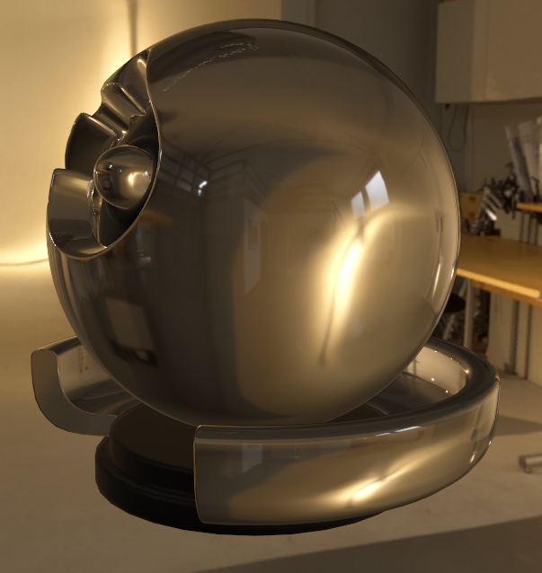
Importantly, on the very edges the image become very blurred. This is more obvious on cubes. Its helps the refraction blend into the reflection better, and generally just gives a more believable result.
New Years Day in Korea
It's the start of the Lunar New Year holiday in Korea. So, 여러분, 새해 복 많이 받으세요! Have a good weekend!
blog comments powered by Disqus