Working some improvements to rectangle lights
Post updated on 2015-12-10
This is just some notes about some ideas I've been playing with lately. I've been thinking about some improvements to the specular highlights for rectangle lights!
The current implementation is based on the method by Michal Drobot in GPU Pro 5. I'm not going to repeat the description here (I'll only give a few details) -- but I recommend buying the book and having a look! It's quite a good method, and interesting read. Drobot describes a very practical method for diffuse and specular for rectangle and disc lights.
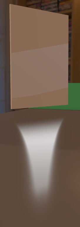
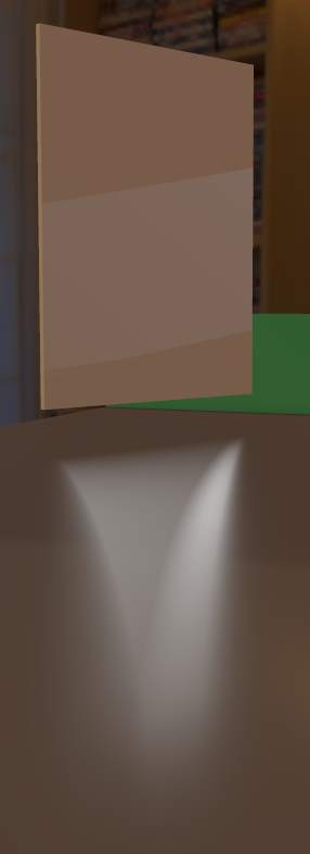
However, at extreme angles, the specular reflection of rectangle lights can sometimes show some distortion.
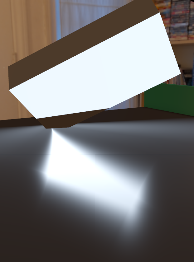
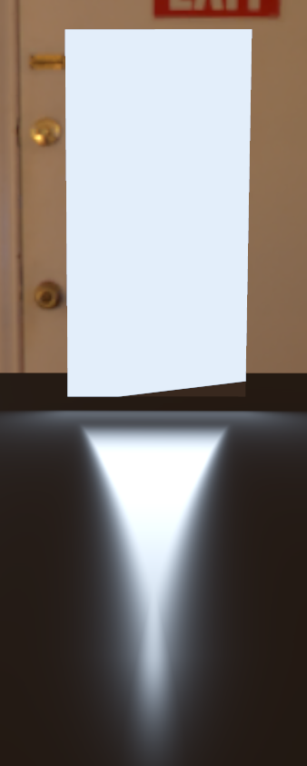
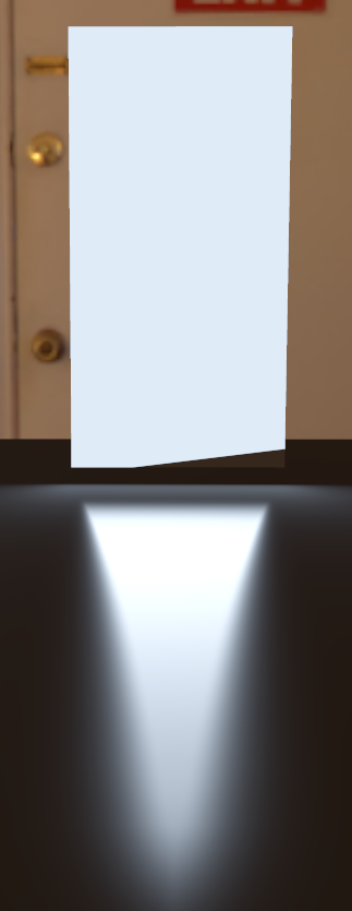
Here is a comparison:
| Original Method | New Method |
|---|---|
 |
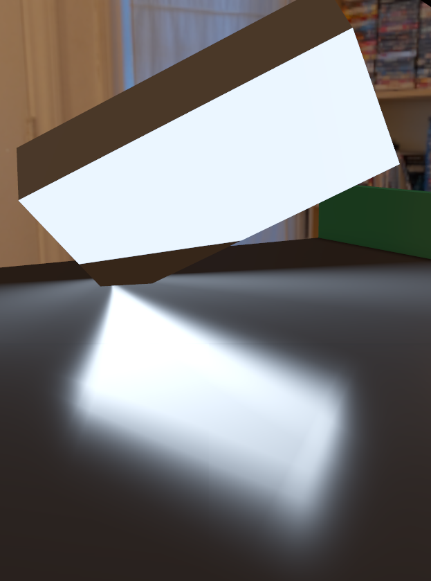 |
It appears quite distorted here, but this is a contrived example. This is a material with high "roughness" but the geometry is completely flat. In a normal scene, flat geometry will probably have a less rough material. And in a less rough material, the distortion is much less visible.
Specular Cone
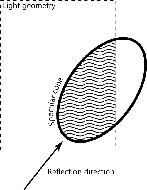
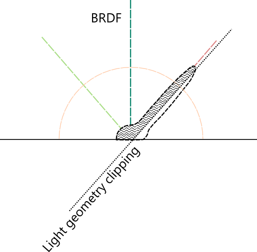
Part of the problem is related to how the integration across the specular highlight is performed. We can calculate a cone that represents the part of the scene that contributes most greatly to the specular for a given point. When calculating the specular for a point, we assume that everything in that cone contributes very strongly to specular, and everything outside of it doesn't contribute at all.
This is a simplification, because really we don't want a binary on/off -- we want to weight all incoming light by the BRDF. But out simplification can be quite good for many cases.
Rectangle and cone intersection
So, once we have our cone, we want to find how much of it is covered by the rectangle light. Ignoring shadows, we can do this by finding the intersection of the cone and the rectangle light.
But, of course, this is quite difficult and expensive. This is starting to go into conic sections, which are a particularly complication type of geometry.
So we need a simplification. Drobot describes a method that is very similar to his method for disc lights.
His method treats the intersection between a plane and the cone as a circle, and then further simplifies it into a square. This method works really well when the light direction is directly towards to the sample point. But on angles, the intersection should start to distort into an ellipse.
See, for example, this diagram from wikimedia commons:

We don't have to care about the parabola or hyberbola cases (because our cone is infinitely long).
Ellipse estimations
Our goal is to find some way to estimate the area of an intersection of that ellipse and a rectangle. And we also need to find the geometric center of that intersection.
Working with the true ellipse here is far too expensive. The method would be extremely complex. However, we can make some estimations. Also, the rectangle and the ellipse are not aligned in any easy way -- so that makes it more complex.
One idea is to use 2 squares, instead of one. We will place the squares near the vertices of the of the ellipse, and balance the area of the squares so that they roughly match the ellipse.
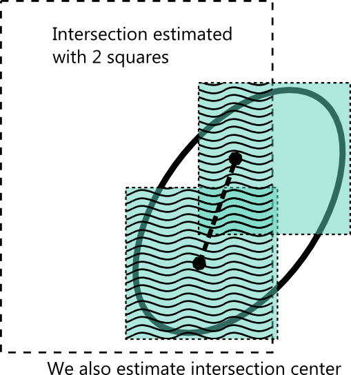
With this method, as the ellipse widens, our simulation takes into account that widening.
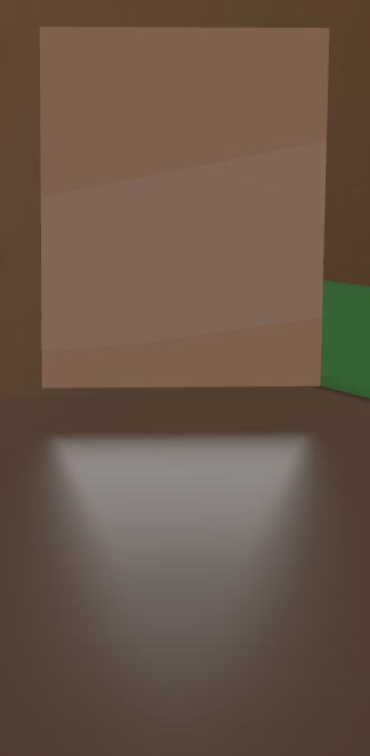
Flat on
2 squares seems to help in the flat-on case, also.
| Original Method | New Method |
|---|---|
 |
 |
As you can see, improved method helps smooth out the result. The light retains it's rectangular shape better.
Representative point tweaks
The goal of these methods is to find a quick estimate to integrating the BRDF across all angles. When we're finding the intersection of the specular cone and the light, we're really trying to estimate the intersection of the light geometry and the BRDF equation. If we could then find the mean of the BRDF in the intersection area, we would have a good estimate of the full integral.
To estimate the mean, we adjust the reflection direction to find a new "representative point" for specular. As Drobot explains in his article, he was working with a phong based BRDF. However, with GGX, I'm finding the equation is very steep, and that small adjustments to the representative point have a huge effect on the result!
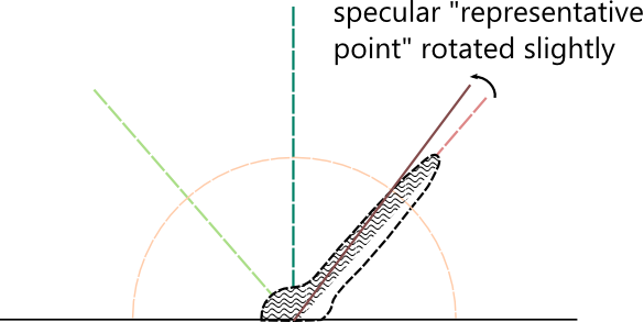
This might be accentuated by the fact that I'm using a very wide angle for the specular cone. The wide angle helps give us really blurry highlights, but it makes some artifact worse.
So I'm finding that we have to be a little more conservative with the representative point. I'm experimenting with taking the average of the intersection center and the unmodified reflection direction.
New artifacts
Unfortunately, the new method can add some artifacts. Sometimes the influence of each square can separate, which can end up giving the impression of 2 separate specular highlights. This can cause some real problems if one square clipped by one side of the light, and the other square is clipped by the other side.
There are also some cases where the single-square method looks better, even though it may be incorrect... With a single square, the highlight will be incorrectly sharp on extreme angles. But it still looks right to the viewer.
Here is an example of the artifacts that can occur in some cases
| Original Method | New Method |
|---|---|
 |
 |
Here the rectangle keeps it's shape better, but the separate effects of the 2 squares starts to become visible.
In a real world situation, this is unlikely to be as visible. Since this is a surface with a high "roughness" we would normally expect there to be a normal map and more geometric detail. That will serve to hide the artifacts.
More screenshots
Here are a few more comparison shots:
| Original Method | New Method |
|---|---|
 |
 |
 |
 |
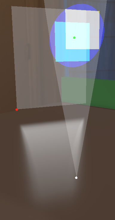
In-engine visualization
You can use the cvar "LightResolveDebugging" to visualize the squares, intersection ellipse and representative points. Type "cv.LightResolveDebugging = True" in the IronPython window in the editor.
blog comments powered by Disqus